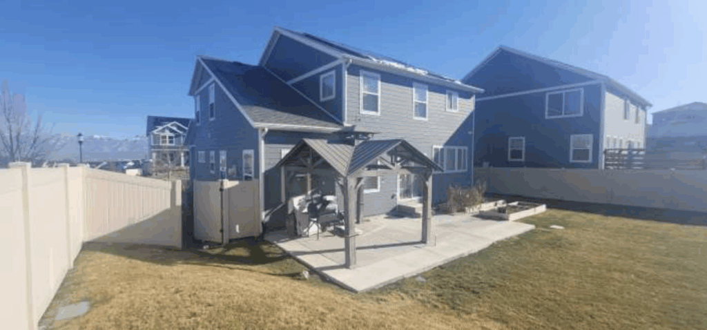
When we arrived at this home in Bluffdale UT, the back yard was quiet, open, and framed by a view the homeowner clearly valued. The space felt settled, as if the house and the land had already come to an agreement long before any new construction was considered. The existing concrete slab sat patiently at the back left corner of the house when viewed from the street, the northwest corner of the structure, poured years ago and left waiting for a purpose. There were no visible step cracks in the slab, no signs of sliding, and no evidence of differential settlement. The foundation beneath it had remained stable, doing exactly what it was intended to do.
The client’s goal was straightforward in theory and complex in practice. He wanted a patio roof, an awning that would provide shade and weather protection while preserving the open feel of the yard. He wanted shade from the sun without feeling confined beneath a low roof. More importantly, he wanted to maintain the views that originally drew him to the property. This was not a request driven by structure, but by request. Still, structure would ultimately determine what was possible.
The proposed patio cover was significant in size. Measuring approximately thirty eight feet long by seventeen feet deep, it was designed to fully cover the existing slab and transform it into a true outdoor living space. At this scale, the structure could not be treated as a light accessory. It would introduce real gravity loads, snow loads, and lateral forces that needed a defined path into the ground. The first question was not how it would look, but how it would provide the needed support.
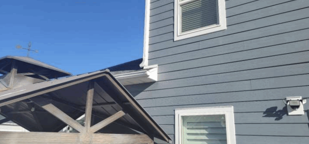
The initial concept involved attaching the patio roof to the drip line of the existing house roof. That attachment point sat roughly eleven feet and one inch above the slab elevation. From an architectural standpoint, this made sense. A higher connection allows for a lower roof pitch, and the client proposed a two over twelve slope to minimize visual impact. Even so, he hoped to reduce the slope further if possible, concerned that the roof line would intrude on views from both the yard and the interior of the home.
This is where engineering constraints became unavoidable.
Utah snow loads place significant demands on roof structures, particularly when load is transferred to elements not designed to carry it. When the engineer evaluated the roof edge trim attachment, the results were clear. At design snow loads, the roof edge trim would be required to support more than one thousand pounds per linear foot. Roof edge trim also known as “fascia boards” are not structural members. They are trim components, intended to carry little more than their own load and the edge of the roofing. Asking them to carry sustained gravity loads introduces risk that cannot be justified, regardless of fastener size or spacing.
This moment is common in residential projects. It is where intention meets physics, and where a clean drawing confronts the realities of load and material behavior.
From that analysis, two primary alternatives were identified.
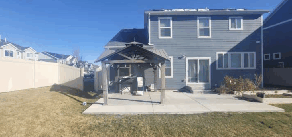
The first option was a fully self supporting patio cover. In this configuration, posts and beams would be installed along the house side of the structure, mirroring the posts along the outer edge. The roof would stand on its own foundation system, supported by dedicated footings rather than relying on the existing house. Loads would transfer from the roof to the beams, down the posts, into the footings, and finally into the soil. This direct load path reduces uncertainty and minimizes the risk of inducing settlement, sliding, or cracking in the existing structure. It also reduces the likelihood of future step cracks forming where new construction meets the original foundation.
Once constructed, the roof could be lightly tied to the house for stability if desired, or left structurally independent. From a performance standpoint, this option places the least demand on the home.
The drawback is primarily visual. Self supporting structures often require deeper beams and additional posts near the house, which can make the roof feel heavier. While structurally sound, the appearance does not always align with a homeowner’s preference for openness.
The second option involved attaching a ledger directly to the structural wall framing of the house, similar to the way an elevated deck is constructed. In this approach, the load bypasses the fascia and roof framing and is transferred into wall studs and rim boards that are designed to bear it. The ledger and ceiling joists would be two by twelve members, with ledger bolts spaced at twelve inches on center. When installed and flashed correctly, this method provides a reliable structural connection.
However, any attachment to an existing structure introduces long term considerations. Penetrations through the building envelope create potential paths for water intrusion. Differential movement between the new patio cover and the existing foundation can introduce stress at the connection. Over time, these stresses can manifest as cracking, localized settlement, or maintenance issues if not properly managed.
A third option was also discussed, though with caution. Attaching the patio roof directly to the roof framing provides favorable elevations and allows for a lower visible roof line. It achieves the client’s visual goals, but it does so by introducing complex load interactions and water management challenges that are difficult to resolve reliably. Additional engineering would be required to address these risks.
Beyond the attachment strategy, the remainder of the structure was clearly defined. The seventeen foot roof joists would need to be minimum two by twelve members at twelve inches on center, or two by fourteen at sixteen inches on center. These joists are designed to carry snow loads and dead loads, not simply support a ceiling. Mid span bracing is required to limit deflection and improve overall performance.
At the outer edge of the roof, the rim beam serves as the primary horizontal support. With spans reaching up to twenty feet between supports, the beam must be a minimum six and three quarter inch by fifteen inch glulam. This engineered member provides predictable strength and stiffness that dimensional lumber cannot reliably achieve.
Supporting the beam are three vertical columns, each a minimum four by four treated post with a maximum height of ten feet. These posts bear on individual spot footings measuring eighteen inches in diameter and thirty inches deep. Each footing includes a twelve by twelve by twelve rebar cage constructed of number four bar, allowing it to function as a small structural pier that resists rotation, settlement, and cracking.
The footings extend at least one inch above finished grade, reducing moisture exposure at the base of the posts. Each post is connected to its footing using a Simpson ABA44Z connector or equivalent, creating a defined connection that resists uplift and lateral movement.
Standing in the back yard in Bluffdale UT, looking at the slab, the house, and the open sky above, it was clear this project was not about adding a simple awning. It was about managing load, protecting the foundation, and preserving the experience of the space. Snow will accumulate regardless of aesthetics. Gravity will act regardless of intention. The structure must be prepared to carry both.
In the end, engineering does not eliminate choice. It clarifies it. A lower slope roof may be possible, but only if the load is carried correctly. Views can be preserved, but not at the expense of long term performance. This patio cover will eventually become a place of daily use, bearing weight quietly, season after season, long after the plans are set aside.